
A current-carrying bus and the electronics recording its current may sit at very different electrical potentials. Transferring a measurement between those domains requires attention to the electrical path as well as the signal.
Isolated current transducers provide a means of separating primary and secondary circuits. Their suitability rests on how the signal crosses that boundary, the installation geometry, the qualified insulation conditions and the output circuit that ultimately carries the measured information.
The Isolation Boundary Follows Electrical Potential
The useful signal amplitude does not identify the potential of the circuit producing it. A small voltage across a shunt can exist on a bus whose potential relative to the control electronics is much higher. Signal-conditioning and isolation circuitry must accommodate that common-mode arrangement, even though the differential voltage being measured remains small.
Galvanic separation interrupts a direct conductive measurement path between electrical domains. In magnetic sensing, the primary conductor’s field carries information about current to the sensing arrangement. Primary current and the secondary signal occupy separate circuits, with insulation providing the required electrical separation between them.
For precision current measurement, the boundary must be located within the actual installation: primary conductor, sensing assembly, secondary electronics and grounding arrangement. Their relationships determine where electrical stress occurs. The design question consequently identifies which circuits require separation and the conditions across that boundary, before selecting a numerical insulation specification.
Magnetic Sensing and Conductor Access Answer Different Questions
Magnetic coupling permits the current information to be obtained without using the bus voltage as the output signal. Fluxgate excitation and sensing coils respond to the conductor’s magnetic effect, producing a secondary measurement. Isolated current transducers can therefore combine electrical separation with AC and DC sensing, while their physical construction determines how the conductor enters the assembly.
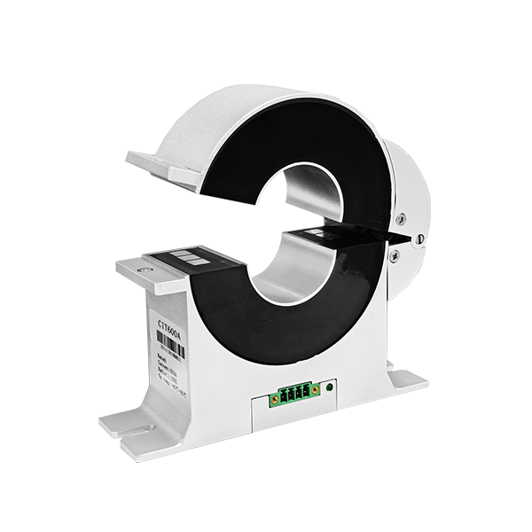
A split magnetic core gives the Hangzhi CIT family access to an existing conductor without requiring disconnection of the primary circuit. Closing the core around that conductor establishes the sensing geometry. Distribution monitoring, energy management and industrial automation are application settings for this retrofit arrangement.
Conductor access and insulation qualification remain distinct considerations. A core that opens can simplify placement around an existing path, but that feature does not authorize installation on energized equipment.
The permissible working conditions depend on the particular model and wider installation. Electrical potential, grounding and installation procedures still govern how the device can be incorporated into the system.
A Withstand Test Includes Its Path and Duration
A dielectric test applies a specified electrical stress for a specified interval. The Hangzhi CIT600A has a primary-to-secondary insulation test of 5 kV at 50 Hz for one minute, together with an impulse withstand test of 10 kV for 50 µs.
The IIT1000 specifies the same voltage, frequency and duration for its corresponding primary-to-secondary test, and the same impulse voltage and duration. The alternating test and brief impulse impose different electrical stresses; each specified duration identifies its corresponding exposure.
Physical distances describe additional paths: CIT600A creepage and clearance between primary and shield are each 11 mm. IIT1000 specifies 11 mm for each distance between primary and shell. Creepage follows an insulating surface; clearance measures the separation through air. The named endpoints prevent an enclosure-related distance from being silently reassigned to a different insulation boundary.
Those figures support precision current measurement by describing aspects of the device’s electrical separation. They do not assign a continuous 5 kV operating voltage to the installation, nor establish a system measurement-category rating. Waveform, time and physical path remain attached to the test evidence, while the actual bus potential and grounding arrangement require their own assessment.
Electrical Separation Still Needs a Valid Output Circuit
Electrical separation leaves current range, secondary loading and dynamic behavior as active measurement constraints. CIT600A nominal ratings are ±600 A DC and 424 A AC RMS; the operating ambient range is −30°C to +75°C. Its 1000:1 ratio gives ±0.6 A rated secondary current, with a typical burden of 2 Ω and a maximum of 5 Ω.
A 2 Ω burden develops 1.2 V at rated output. The CIT600A has a −3 dB bandwidth of 350 kHz; step response reaches 90% of nominal DC current within 2 µs at an input slew rate of 100 A/µs.
The CIT600A secondary current-output circuit must remain connected whenever primary current flows or the device is powered. That requirement belongs to the signal path despite the isolation between primary and secondary. Isolated current transducers still depend on compatible receiving circuits; electrical separation alone does not establish that the output remains interpretable.
IIT1000 illustrates a further boundary during overload. Above its specified measuring range, operation leaves the zero-flux state and secondary current ceases to be proportional to primary current.
The insulation construction is unchanged, but an output recorded in that state no longer represents primary current through the normal ratio. Proportional operation resumes only when primary current returns within the specified measuring range.
A short withstand test leaves the installation’s continuous operating conditions to be established separately. Insulation paths and output requirements become separate installation checks for CIT and IIT devices made by Hangzhi. Precision current measurement depends on both electrical separation and a valid proportional signal under the intended current, loading and environmental conditions.
Component test evidence describes the tested device; qualification of the installed arrangement additionally concerns the potentials, grounding and operating stresses present throughout that arrangement.

